Electrical Resistance Circuits
Electrical Resistance Circuits – In the electrical circuit, maybe you often find some electrical resistance which is arranged by a joint program. The obstacles are not only resistors but all electrical devices.
In general, the series of electrical resistance can be divided into two, namely Series Barriers and Parallel Barriers. In making series series or even parallel resistance a minimum of two obstacles is needed.
And if you want to create a series-parallel resistance is needed 3 resistance. Each type of obstacle network has its own advantages and disadvantages.
On this occasion YukSinau.co.id will discuss the complete range of electrical resistance in detail. Let's consider the following explanation.
Table of Contents
Electrical Resistance Circuits
Barriers can be assembled by using 3 ie way: parallel series, series and parallel series. Each series has different characteristics and conditions.
Before discussing more about the electrical resistance circuit let us know the symbol symbols that are in the electrical resistance circuit.
- I = strong current (A)
- V = Potential difference(V)
- R = Obstacles (Ω )
Series Barriers

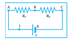
Series obstacles are two obstacles that are arranged in a sequential way. The circuit arranged in series will form an unbranched electrical circuit. In a series of strong electric current flowing has the same magnitude at each point.
The purpose of obstacles in series is to increase the value of the electrical resistance and to divide the potential difference from the voltage source. The series of obstacles arranged in series can be replaced by using a barrier which can be called a series replacement obstacle.
Examples of series obstacles are , suppose there is 4 lamps with resistance respectively R1, R2, R3 and R4 are arranged in series and then connected to batteries that have voltage (V) cause an electric current to flow for I.
So that the voltage of V is distributed to the four obstacles which respectively V1, V2, V3 and V4 will apply :
V = v1 + V2 + V3 + V4
Information :
V1 = Voltage 1
V2 = Voltage 2
V3 = Voltage 3
V4 = Voltage 4
If you look at Kirchoff's Law in the series) the following equation applies :
I = I1 = I2 = I3 = I4
Information :
I1 = Electric Current 1
I2 = Electric Current 2
I3 = Electric Current 3
I4 = Electric Current 4
Another example is when there are some obstacles to the tie, then connected to the voltage source, then each of the obstacles was electrified by an equal amount of electricity. From the following set of barriers is obtained:
- large substitute barriers (RS): RS = R1 + R2
- large strong current flowing (I):

- VAC = VAB + VBC I . Rs = I . R1 + I . R2
Parallel Obstacles

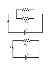
Parallel barriers are two electrical obstacles which are arranged together side by side. The electrical circuits formed by the parallel resistance will be in the form of branches and have more than one electric current path. The series of parallel barriers can be replaced by a barrier called a parallel barriers.
In a parallel circuit the flowing current will be divided at each obstacle. The amount of current that passes through each obstacle is different. Keep in mind that the parallel parallel array or potential difference in each resistor has the same value.
Based on the information above, it can be concluded that in the parallel sequence the following equation applies .
| Vtotal = V1 = V2 = V3 =… Vn Ip = I1 = I2 = I3 = …. In |

Information :
Ip = Total Strong Current
Vtotal = Total Total Voltage
Rp = Total Obstacles
I1 = Strong current 1
I2 = Strong current 2
I3 = Strong Current 3
V1 = Voltage 1
V2 = Voltage 2
V3 = Voltage 3
R1 = Obstacles 1
R2 = Obstacles 2
R3 = Bridge 3
The amount of current I can be formulated as follows:

Information :
I = Strong current
V = voltage
R = Obstacles
Barriers to parallel replacement can be formulated as follows :

Series-Parallel Barriers

The picture above is a picture that shows a series-parallel resistance series. To calculate the replacement resistance there is no standard formula used. But it can be searched gradually.
In the circuit above R2, R3 and R4 are part of a parallel circuit, as a replacement barrier for R2, R3 networks, and R4 is Rp. Then, R1 and R2 are series. So that the replacement barrier for Rs is a combination of R1 and Rp.
Sample Questions
1 . There are three obstacles, each of which is of value 6:, 4:, and 3: arranged in series. Determine the replacement bottleneck!
Known : a. R1 = 6: b. R2 = 4: c. R3 = 3:
Asked: Rs = … ?
Answer : Rs = R1 + R2 + R3 = 6 + 4 + 3 = 13
So, the successor obstacle is 13
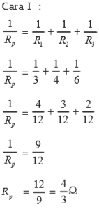
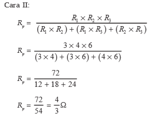
2. Available 3 obstacles that have milai respectively- respectively 3, 4 and 6 which are arranged in parallel. Calculate the block replacement for the circuit!
Known :R1 = 3 R2 = 4 R3 = 6 :
Asked: Rp … ?
Answer :


3. Three obstacles each for 4 ohm, 3 ohm, and 8 ohm, arranged in parallel. If strong current flows 4 ampere, calculate the potential difference!
The solution:
Known: R1 = 4 Ω R3 = 8 Ω R2 = 3 Ω I = 4 A
Asked: V = … ?

That's all the discussion about the Electrical Resistance Series may be useful as physics learning materials. To find out about other physics materials, visit the following article.
Other Articles :
- Gauss's Law
- Lenz's Law
- Electromagnetic wave
- Black Body Radiation
- Potential Energy Formula
- Unidirectional Electric Current
- Solid substance
- Gas Laws
The post Electrical Resistance Series appeared first on YukSinau.co.id.
